


Long-Range Ethernet Data Link for UAV & USV

8 W PA + tracking antenna, line of sight300+ km - Full-duplex data rate (64QAM)
26.8 Mbps ×2High-speed mobile reception1000+ km/h - Startup time
- 5 s
Overview
[ Architecture ]
A transmitter and a receiver behind one antenna
Ethernet ×2
UART
Ethernet switch 4-port
SoC
Ethernet bridge
COFDM transmitter
COFDM receiver
PA
Diplexer
Antenna
RF front end — outside the base module
Ethernet ×2
UART
Ethernet switch 4-port
SoC
Ethernet bridge
COFDM transmitter
COFDM receiver
PA
Diplexer
Antenna
RF front end — outside the base module
- Transmit
- Receive
- Ethernet / serial
Throughput · each direction
- 64QAM
-
26.8 Mbps - 16QAM
-
17.8 Mbps - QPSK
-
8.9 Mbps
[ Range ]
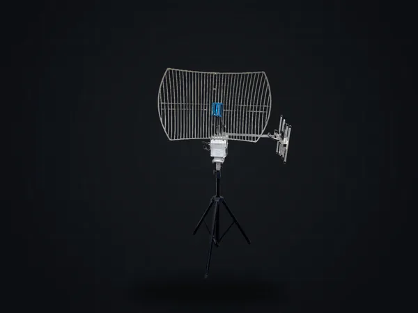
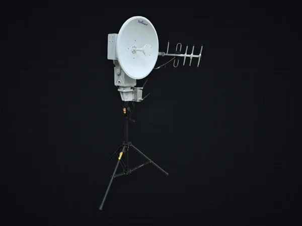
300+ km takes the tracking antenna
- Standard omni-dipole
-
20– 30+ km - Patch antenna
-
60– 90+ km - Auto-tracking antenna
-
200– 300+ km
Line-of-sight range (km)
0100200300
[ Applications ]
Ethernet, carried across the gap
- Aloft
ETL-210A
- Ground station
HAT-110 +ETL-210A
- Receive-only stations
- Share the downlink — no limit on number
- Command centre
- Ethernet — any IP device
- Aloft
ETL-210A
- Ground station
HAT-110 +ETL-210A - → Command centre · Ethernet — any IP device
- Receive-only stations
- Share the downlink — no limit on number
- Downlink · video + data
- Uplink · C2
- Receive-only stations
Independent channels · up to 300+ km
Where it is used
- Aircraft
- Ships
-
High-speed trains - Subways
- Remote islands
- Mountainous regions
- Emergency evacuation and rescue networks
Specifications
System features
- 01
With a high-power amplifier, achieves300+ km full-duplex range - 02
Supports high-speed reception at over1000 km/h - 03
Independent uplink/ downlink channels (FDD) — stealthy, strongly jam-resistant - 04
Transparent bidirectional Ethernet plus RS-232 /RS-485 /S.BUS/ UART - 05
Military-grade AES-128 /AES-256 encryption - 06Full-duplex and broadcast dual mode — in broadcast mode, unlimited simultaneous RVT (Remote Video Terminal) receivers
- 07Active tracking-antenna integration with dynamic auto north-finding
- 08
Flexible custom bands from 100 MHz to5.8 GHz
RF parameters
- RF frequency (base)
100– 2500 MHz ·1 kHz step- Bandwidth
1 / 2 / 2.5 / 3 / 4 / 5 / 6 / 7 / 8 MHz - Modulation
- COFDM · FFT 2K/4K/8K
- Constellation
- QPSK / 16QAM / 64QAM
- Code rate
- 1/2 · 2/3 · 3/4 · 5/6 · 7/8
- Guard interval
- 1/4 · 1/8 · 1/16 · 1/32
- Digital attenuator
0 to − 47 dB ·1 dB step
System
- Data rate
528 kbps –26.8 Mbps - Throughput by constellation
-
- 64QAM
26.8 Mbps - 16QAM
17.8 Mbps - QPSK
8.9 Mbps
Each direction
- 64QAM
- Connectors
SMA 50 Ω ×1 · RJ-45 ×2 · UART/RS-232 ×2- Encryption
AES-128 /AES-256 - Power
DC 12– 30 V ·550 mA –3 A (by PA)- Operating temp.
− 40 °C ~70 °C - Dimensions / weight
200 × 135 ×70 mm ·1160 g (w/8 W PA)- Compliance
IEEE 802.3af/ at · RoHS
Ordering
ETL-210A-B Base module (w/o PA/ filter) ETL-210A-PATV Optimized 400– 800 MHz ·built-in 200 mW PAETL-210A-PA2.4G Optimized 2.2– 2.4 GHz ·built-in 8 W PA (39 dBm )
Receiver performance
- Max input
> + 5 dBm - Sensitivity
-
-
1 MHz < − 99 dBm -
1.5 MHz < − 98 dBm -
2 MHz < − 96 dBm -
2.5 MHz < − 95 dBm -
3 MHz < − 95 dBm -
4 MHz < − 94 dBm -
5 MHz < − 92 dBm -
6 MHz < − 91 dBm -
7 MHz < − 90 dBm -
8 MHz < − 90 dBm
Measured at 2K · 16QAM · CR 2/3 · GI 1/8, single antenna
-
Transmitter performance
- RF output level
-
-
100– 470 MHz 5 dBm -
470– 950 MHz 5 dBm -
950– 1900 MHz 0 dBm -
1900– 2500 MHz − 5 dBm
ETL-210A-B base module, without PA -
- MER
-
-
V-band > 39 dB -
470– 950 MHz > 39 dB -
950– 1900 MHz > 36 dB -
1900– 2500 MHz > 34 dB
Typical, at − 5 dB digital attenuation -
- Spectrum shoulder
> 48 dB - Phase noise
< −114 dBc @ 100 kHz - Carrier suppression
> 42 dB
Range with 8 W PA (LOS)
- Standard omni-dipole
20– 30+ km - Patch antenna
60– 90+ km - Auto-tracking antenna
200– 300+ km
[ Next steps ]
Bring the ETL-210A into your project
Tell us your vehicle, range and band, and HiDes will help plan the configuration. The full datasheet is available by email on request.
info@hides.com.tw ·
Works with