
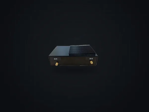
Long-Range Video Transmitter for UAV & USV

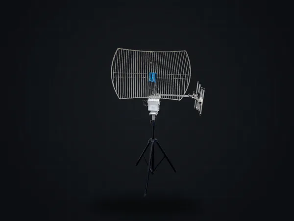
8 W PA + tracking antenna (LOS)300+ km - COFDM video channel, maximum
16 Mbps - C2 duplex air rate, FEC off
230.4 kbps - Max mesh nodes (swarm)
- 16
Overview
[ Product film ]
Fly farther. Stay linked. Stay unseen.
[ Link architecture ]
Video and control travel separately
COFDM video
C2 telemetry Full duplex
Band allocation
[ Inside ]
Two radios in each enclosure
Ethernet
Flight controlUART
UARTdata mux
SoC
COFDM transmitter HV-380 / HV-390
BPF
PA
C2 radio HRM-110 / HRM-120
BPF
COFDM video
C2 return channel
Ethernet
UARTdata mux
Flight controlUART
SoC
COFDM transmitter HV-380 / HV-390
C2 radio HRM-110 / HRM-120
BPF
BPF
PA
COFDM video
C2 return channel
COFDM video, one-way C2, two-way - Ethernet / serial
Interfaces, aloft and ground
- Serial
UART · RS-232 ·RS-422 ·RS-485 - RCS.BUS
- EthernetMAVLink · RTP H.264 / H.265 · RTSP
- ControlAT commands · UDP
What each unit contains
- Aloft
COFDM transmitter HV-380 /HV-390 + C2 radioHRM-110 - Ground
COFDM receiver HV-130 + C2 radioHRM-110
[ Ground side ]
One stream over the air, any number of viewers
IP camera RTP · H.264 / H.265
Flight controller MAVLink · UART1
Aloft unit RTSP / RTCP handled here
Ground unit RTP agent · up to 3 streams
Ground control station MAVLink
RTP receivers any number, e.g. ATAK
IP camera RTP · H.264 / H.265
Flight controller MAVLink · UART1
Aloft unit RTSP / RTCP handled here
Ground unit RTP agent · up to 3 streams
Ground control station MAVLink
RTP receivers any number, e.g. ATAK
- RTP video
- C2 / MAVLink
- Ethernet / serial
What RTP agent mode changes
The RTSP/ RTCP handshake never crosses the air — each end answers it locally. - Only the RTP video stream goes over the COFDM link, one way.
- Video keeps flowing if the C2 channel is jammed.
- The ground station transmits nothing on the video channel.
- Any number of RTP receivers can join, such as ATAK terminals.
- Up to 3 RTP streams are relayed at once.
MAVLink relay
- Flight controller connects to UART1 on the aloft unit.
- The ground unit puts MAVLink on Ethernet.
- Ground control station and tracking antenna read the same stream.
[ C2 anti-jamming ]
Four ways to keep command and control
- 01
Background spectrum scan The band is surveyed while the link runs, so a clear channel is known before it is needed.
- 02
Channel switching on the fly The C2 frequency is changed remotely without taking the link down.
- 03
FHSS / DSSS Frequency-hopping and direct-sequence spread spectrum on the C2 radio.
- 04
Link redundancy
A second link can be configured to take over when the first is lost.
[ Range ]
The antenna moves the number further than the power does
5 dBi omni-
> 20 km 8 dBi patch-
> 30 km 21 dBi grid + tracking-
> 120 km
5 dBi omni-
> 25 km 8 dBi patch-
> 40 km 21 dBi grid + tracking-
> 160 km
5 dBi omni-
> 40 km 8 dBi patch-
> 70 km 21 dBi grid + tracking-
300+ km
Line-of-sight range (km)
0100200300
Specifications
System features
- 01
Wide tunable range ( 400+ MHz ) with professional-grade MER - 02
Dynamic channel switching — remote on-the-fly retune to dodge jamming - 03
Selectable bandwidth 2– 8 MHz - 04
Transparent UART / S.BUS / RS-232 /RS-485 / Ethernet - 05
AES-128 andAES-256 anti-eavesdropping encryption - 06Standard RTSP / RTP unicast & multicast video
- 07Mesh networking with up to 16 nodes for swarm applications
COFDM RF transmitter
- Frequency
FV-800 : 1800–2000 / 2000–2500 / 2250–2500 MHz ·FV-810 : 2100–2700 MHz ·1 kHz step- Bandwidth
2 / 3 / 4 / 5 / 6 / 7 / 8 MHz - FFT
- 2K / 4K / 8K
- Code rate / GI
- 1/2–7/8 · 1/4–1/32
- Customization
400 MHz –2.7 GHz - Output power
28.5 dBm (1 W ) ·31.5 dBm (2 W ) ·38 dBm (8 W )
C2 data link
- Frequency
470–490 / 500–520 / 1200– 1300 MHz - Bandwidth
150 kHz @115.2 kbps ·250 kHz @230.4 kbps - Modulation
- 2/4 (G)FSK · OQPSK DSSS · (G)MSK · OOK
- Output power
30.5 dBm (1 W ) ·32 dBm (2 W ) ·35 dBm (4 W )
Range (LOS)
1 W PAOmni > 20 km · patch >30 km · tracking antenna >120 km 2 W PAOmni > 25 km · patch >40 km · tracking antenna >160 km 8 W PAOmni > 40 km · patch >70 km · tracking antenna300+ km
System
- Interface
RJ-45 · UART /RS-232 /RS-485 / S.BUS- Power supply
9– 30 V DC- Weight
-
-
Aloft · 1 W +1 W 280 g -
Aloft · 2 W +4 W 370 g -
Aloft · 8 W +4 W 850 g - Ground
240 g - Fan / heatsink
63 g each
Excluding antenna and cable
-
- Dimensions (W × D × H)
-
- Aloft enclosure
160 × 110 ×35 mm - Ground enclosure
145 × 90 ×35 mm - Aloft PCBA
100 × 70 ×12 mm - Ground PCBA
85 × 60 ×12 mm -
External 2 W PA90.5 × 50 ×15 mm -
External 8 W PA150 × 120 ×22 mm - Fan
80 × 80 ×20 mm - Heatsink
80 × 80 ×7 mm
Enclosure sizes exclude fan and heatsink
- Aloft enclosure
Peak current @ 24 V -
-
1 W +2 W Aloft 600 mA · ground325 mA -
2 W +5 W Aloft 1000 mA · ground325 mA
8 W +5 W model: to be announced -
- Operating temp.
− 10 °C ~70 °C
Ordering
FV-800-2025A470A 2000– 2500 MHz · C2 470–490 · PA1 W /1 W FV-800-2025B470D 2000– 2500 MHz · C2 470–490 · PA2 W /4 W FV-800-1820B470D 1800– 2000 MHz · C2 470–490 · PA2 W /4 W FV-800-2225H470D 2250– 2500 MHz · C2 470–490 · PA8 W /4 W FV-810-2127A470A 2100– 2700 MHz · C2 470–490 · PA1 W /1 W FV-810-2127A1200B 2100– 2700 MHz · C2 1200–1300 · PA1 W /2 W
※ PA codes: A=1W · B=2W · D=4W · E=5W · H=8W. Higher-power amplifiers available for ultra-long-range applications.
[ Next steps ]
Bring the FV-800 / FV-810 into your project
Tell us your vehicle, range and band, and HiDes will help plan the configuration. The full datasheet is available by email on request.
info@hides.com.tw ·
Works with
